In this first tutorial, we're going to cover:
- Starting a project, pre-requisites
- Key concepts - parts and assemblies
- Simple assembly of a printed part and an existing vitamin
- Using the vitamin catalogue
- Use of utility tools and assembly guide generation
- Using the sandbox
- Printing the STL
The outcome of this tutorial is a basic quad-copter frame sized to fit the motors from the Hubsan X4 (or similar). Our OpenSCAD model will contain the frame itself (as a single printable part) and a representation of the motors. The model will not contain the battery, flight controller, wiring, etc (this will be tackled in the later tutorials).
If you have the relevant parts, then at the end of the tutorial you will be able to print out the frame for test assembly, and even fly the frame by taping the battery/flight-controller to it.
There are various utility scripts included in the template project to aid the design process, they are all written in Python (tested against v2.7.9). As such, you will need to ensure you have a compatible version of Python installed along with a couple of dependencies:
- PIL - the Python Image Library - use:
pip install pillow - Pystache - the Pystache template library - use:
pip install pystache
The framework can generate animated assembly guides, but relies upon the following:
- ffmpeg
- convert (ImageMagick command line)
Once you have the pre-requisites installed, you need a local copy of the framework from which to bootstrap a new project - download or clone it from github, for the sake of the tutorial, we'll assume the framework is stored in /OMDF:
To start a new project:
- Open a terminal and navigate to the /OMDF/scripts directory
- Run
./startaproject.py <in-dir> QuadFrame. Replace with the directory within which you would like to create the project (e.g.~/Documents).
The startaproject.py script will:
- Create the directory structure for the new project
- Setup standard config files
- Setup a root .scad file
- Init git
- Setup and clone the framework as a submodule within the
QuadFrame/hardware/frameworkdirectory
Once the project is created, you can optionally add it to a site like .
The project files are all contained within a top-level "hardware" directory, on the assumption you will add other top-level directories for software development, notes, etc.
You will find the following directories within /hardware:
| Directory | Contains |
|---|---|
| . | Top-level machine .scad file (e.g. QuadFrame.scad), generated by the framework |
| assemblies | SCAD files that describe all the assemblies/sub-assemblies |
| build | files generated by the framework during the build process (you can ignore these!) |
| config | Global configuration files |
| cutparts | SCAD files for any cut parts |
| docs | Generated documentation including assembly guide(s) and vitamin catalogue |
| framework | the framework, embedded as a git submodule |
| images | Generated images of the machine |
| printedparts | SCAD files for the printed parts of your machine |
| sandbox | Playground for developing parts, assemblies, etc |
| vitamins | Rendered images of non-printable parts (e.g. motors, switches, nuts, bolts), the actual vitamin source code is contained within the framework |
You can check everything is laid out and working correctly by opening the hardware/QuadFrame.scad file. OpenSCAD should open and preview a small cube. You shouldn't have any error messages in the console. :)
You can also test the Python utility scripts are working properly by:
- Open a terminal
- Navigate to the
/hardware/frameworkdirectory - Run
./build.shto run the build process - this will take a while!
A lot of status messages should fly by, with the last line being "Build Complete". If you look in the /hardware/images directory, you should find a single image file QuadFrame_view.png showing a small cube. This image will get a lot more interesting once we've created some parts!
Models of complete machines are comprised of a few fundamental building blocks:
- Vitamins - are the physical parts you use as-is (not make) within your machine (e.g. screws, motors, batteries), majority of these should be reusable between different projects
- Printed-parts - are the parts you will print on a 3D printer
- Cut-parts - are the parts you make using a non-printing fabrication process (e.g. cutting, drilling, bending)
- Assemblies - represent how the vitamins, printed-parts and cut-parts should be put together
Vitamins, printed-parts and cut-parts are collectively referred to as parts.
Assemblies are typically arranged in a hierarchy, with a top-level assembly containing a combination of parts and sub-assemblies.
A typical design process will rapidly iterate over the following steps:
- Import, or develop, the key vitamins (often drive systems and electronics)
- Layout groups of vitamins within assemblies
- Develop the printed parts to hold the vitamins together
- Print, test, repeat
Project teams can often tackle these steps in parallel, with team members owning development of the various vitamins, printed-parts and assemblies. Collaboration techniques are covered in a later tutorial.
The machine SCAD file (/hardware/QuadFrame.scad) is primarily a "wrapper" around your top-level assembly, but it also links in the global configuration file (/hardware/config/config.scad) and provides information to the build process about the project.
We'll return to edit this file once we've created our top-level assembly.
The top-level, or final, assembly is where you define how all the various parts come together. It is purely for on-screen display, either in OpenSCAD or in the assembly guide, but is critical to helping you correctly model your machine. It's also one of the best places to start a new design.
Creating a new assembly file requires a few steps, however, there is a utility script that automates most of the process:
- Open a terminal and navigate to
/hardware/framework/scripts - Run
./adda.py assembly Final "Final Assembly"
The parameters for adda.py represent:
- assembly - Create an assembly (the same script can also be used to create other parts)
- Final - this is both the filename for the new assembly (the .scad extension will be added automatically) and the prefix to the module name (e.g. FinalAssembly())
- "Final Assembly" - this is the descriptive name of the assembly, as used in the generated guides
The adda.py script will:
- Create a templated assembly file at:
/hardware/assemblies/Final.scad - Add the assembly to the global configuration (
/hardware/config/assemblies.scad) - Create a sandbox file to aid with developing your assembly at:
/hardware/sandbox/assembly_FinalAssembly.scad
Open the assembly file (/hardware/assemblies/Final.scad) in your text editor, it should look something like this:
module FinalAssembly () {

    assembly("assemblies/Final.scad", "Final Assembly", str("FinalAssembly()")) {

        // base part

        // steps
        step(1, "Do something") {
            view(t=[0,0,0], r=[52,0,218], d=400);

            //attach(DefConDown, DefConDown)
            //      AnotherAssembly();
        }

    }
}
The FinalAssembly module represents the assembly, and critically, it contains as assembly() statement. The assembly() statement tells the build-system to treat this as an assembly and to show the assembly steps in generated guides. The assembly statement takes three parameters:
- The location of the the current file (relative to the
/hardwaredirectory) - The description of the assembly, as used in generated guides
- How to call the module from within OpenSCAD scripts - this is critical to the build system
Within the assembly() statement are:
- A call to the base part - the part you start with when assembling this assembly, typically this is a printed part (e.g. a base plate), but may also be a key vitamin that has other parts attached to it (e.g. a motor)
- A sequence of assembly steps - defined within
step()statements
A step() statement takes two parameters:
- The step number (use integers, from 1 upwards)
- The assembly instructions for the step - these are inserted directly into the assembly guide and can contain markdown syntax
Each step() statement then contains:
- Any views that should be rendered by the build system and included in the assembly guide
- The part(s) that should be attached to the base part in this assembly step
Don't worry about the contents of the step() statement for now, we'll come back to that later in the tutorial.
We have one more small change to make before we start integrating parts into this assembly - we need to add this assembly to our machine file:
- Open '/hardware/QuadFrame.scad'
- Replace from
//Top level assemblytocube([10,10,10])withFinalAssembly(); - Save the changes
At this point, opening /hardware/QuadFrame.scad in OpenSCAD will show a blank screen, as the FinalAssembly doesn't yet contain any parts!
As mentioned above, the best way to start a designing a part is by first laying out any associated vitamins within an assembly. With that in mind, we'll first layout the 4 motors for our quadcopter, before designing a printed frame to hold them.
All of the library vitamins are located in the /hardware/framework/vitamins directory. The associated source code should all be clearly structured, but reading through lots of SCAD files is not the quickest way to get started. Instead, the framework generates a Vitamin Catalogue to make life easier.
Like all of the auto-generated documentation, it is produced in two formats: markdown and HTML. The HTML version is actually dynamically rendered from the markdown file, which unfortunately means it can only be viewed through a local web server (due to browser security restrictions). If you have a local web server configured, then navigate to /hardware/framework/docs/VitaminCatalogue.htm. Otherwise, grab yourself a markdown viewer (e.g. LightPaper) or text editor and open /hardware/framework/docs/VitaminCatalogue.md.
NB: You can also view the live reference catalogue on github here: Vitamin Catalogue
You should see a long list of vitamins that are available for use in your project, including all the part variants that can be generated by each vitamin SCAD file. Alongside a description and image of each part is the associated call statement that you should use in your project.
Locate the section for the DCMotor.scad file and look for the CL072014 DC Motor part. The associated call statement should be DCMotor(DCMotor_CL072014). This is a basic model of the motors used in the Hubsan X4 and is what we'll use to help layout our printable frame.
Now we've located an appropriate vitamin in the library, we need to add it to our project. This is a two step process:
- Make sure the relevant vitamin SCAD file is included in our global configuration
- Call the appropriate vitamin from within an assembly
To include the DCMotor.scad file in our global configuration:
- Open
/hardware/config/vitamins.scadin your text editor - Append this line:
include <../framework/vitamins/DCMotor.scad>
The /hardware/config/vitamins.scad file lists all the include statements for vitamins we are using in our project. It's best to keep these in alphabetical order for readability.
Now let's add the DCMotor(DCMotor_CL072014) call to our assembly. Open /hardware/assemblies/Final.scad in your text editor and modify the step() statement to the following:
step(1, "Insert the motors") {
    view(t=[0,0,0], r=[52,0,218], d=400);

    attach(DefConUp, DCMotor_Con_Face)
        DCMotor(DCMotor_CL072014);
}
If you open /hardware/QuadFrame.scad in OpenSCAD, you should see the DC motor model centered on the origin. Clearly we are going to need more than one motor, but first let's specify some global machine parameters to define the layout.
Global machine parameters are available in every assembly, part, etc and should be used for the key parametric values of your design. For our quadcopter layout, we'll keep things simple and assume the frame will be symmetrical with the arms arranged in a cross - the X layout. This means we only need to define one parameter for the length of the arms:
- Open
/hardware/config/config.scadin your text editor - Insert the following line below
// Global design parameters:ArmLength = 85/2; - Save and close the file
This ArmLength is based on the Hubsan X4 having a diagonal distance of approx 85mm between motors. You're welcome to choose a different ArmLength for your design.
Now we have our ArmLength global parameter, we can roughly layout the motors within the assembly. To do this, let's change the code where we previously attached a single motor to:
for (i=[0:3])
    rotate([0,0, 45 + i*90])
    translate([ArmLength,0,0])
    attach(DefConUp, DCMotor_Con_Face)
    DCMotor(DCMotor_CL072014);
Previewing the machine in OpenSCAD should now show 4 motors laid out in a cross.
Now it's time to create a new printed part for the frame - as with the assembly, the Python utility automates the process:
- Open a terminal and navigate to
/hardware/framework/scripts - Run
./adda.py printedpart Frame Frame
The adda.py script will:
- Create a templated printed-part file at:
/hardware/printedparts/Frame.scad - Add the printed-part to the global configuration (
/hardware/config/printedparts.scad) - Create a sandbox file to aid with developing your part at:
/hardware/sandbox/printedpart_Frame.scad
Open the printed-part file (/hardware/printedparts/Frame.scad) in your text editor, it should look something like this:
// Connectors
Frame_Con_Def = [[0,0,0], [0,0,-1], 0,0,0];

module Frame_STL() {
    printedPart("printedparts/Frame.scad", "Frame", "Frame_STL()") {

        view(t=[0,0,0],r=[72,0,130],d=400);

        if (DebugCoordinateFrames) frame();
        if (DebugConnectors) {
            connector(Frame_Con_Def);
        }

        color(Level3PlasticColor) {
            if (UseSTL) {
                import(str(STLPath, "Frame.stl"));
            } else {
                Frame_Model();
            }
        }
    }
}


module Frame_Model()
{
    // local vars

    // model
    difference() {
        union() {
            cube([10,10,10]);
        }


    }
}
Don't worry t0o much about the contents, for now let's add the Frame to our assembly:
- Open
/hardware/assemblies/Final.scadin your text editor - After the
// base partcomment add the line:Frame_STL(); - Save and close the file
At this point, if you preview the machine in OpenSCAD you won't see anything new except for a warning in the console stating WARNING: Can't open import file '"printedparts/stl/Frame.stl"'.. This is because our new part is still in development and we've not yet run the build tools to generate the associated STL.
This is where the sandbox comes into play - it allows us to work on new parts before running the build process. Open the /hardware/sandbox/printedpart_Frame.scad file in OpenSCAD and you should be able to see the new part (just a small cube).
We can now refine our frame design within the Frame_Model() module at the bottom of the /hardware/printedparts/Frame.scad file.
Here's a basic frame design to get you started - refine/change it as much as you'd like:
module Frame_Model()
{
    l = ArmLength;
    aid = DCMotor_RearCan_OD(DCMotor_CL072014) + 0.5;  // dia of motors, inc tolerance
    aod = aid + 2 * 2.5; // outer dia of motor holders
    ll = 15;  // leg length
    w = 25;  // width of central plate

    difference() {
        union() {

            // arms
            for (i=[0:3])
                rotate([0,0,45 + i*90]) {
                    // Nice rounded end
                    hull() {
                        translate([l, 0, -tw])
                            cylinder(r=aod/2, h=tw);

                        translate([l-aod, -tw/2, -tw])
                            cube([1, tw, tw]);
                    }

                    // Rest of the arm
                    translate([0, -tw/2, -tw])
                        cube([l, tw, tw]);

                    // basic landing leg
                    translate([l-aod, -tw/2, -ll])
                        cube([tw, tw, ll]);
                }

            // central plate for fixing battery and flight controller to
            translate([-w/2, -w/2, -tw])
                cube([w, w, tw]);
        }

        // holes for motors
        for (i=[0:3])
            rotate([0,0,45 + i*90])
            translate([l, 0, 0])
                cylinder(r=aid/2, h=100, center=true);


    }
}
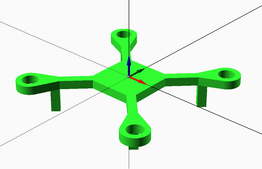
The resulting frame should look like this in OpenSCAD:
Now we have a basic frame design, we can run the build process and explore the results:
- Open a terminal and navigate to
/hardware/framework - Run
./build.sh
The build process will take a minute or so to complete, you can see a fairly verbose output in the terminal window. Once the process has completed, let's check a few things:
- Open the machine SCAD file
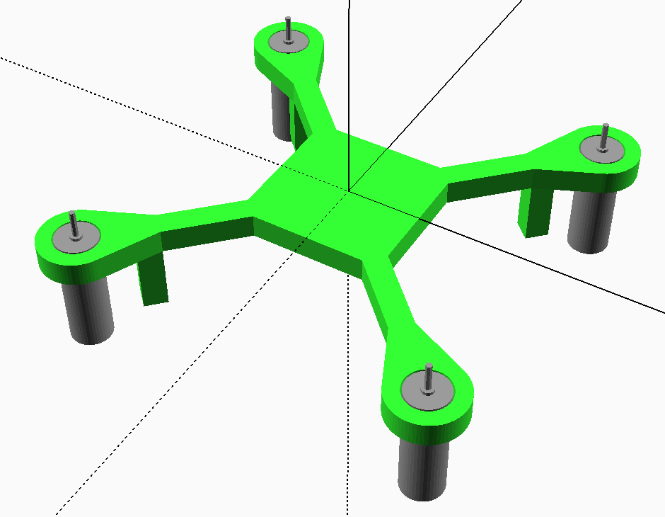
/hardware/QuadFrame.scadin OpenSCAD, you should now see the frame with motors
- Open
/hardware/docs/QuadFrameAssemblyGuide.htm(served from a web server) or open/hardware/docs/QuadFrameAssemblyGuide.mdin a markdown viewer - you should see a section for the Bill of Materials and assembly instructions for the Final Assembly (albeit one step) - Similarly, there is a:
- Printing Guide - listing the parts that need to be printed and approx volume of plastic/cost
- Sourcing Guide - listing where you can buy the various vitamins (which will be blank at this point, as we've not defined any sources)
- Browse to
/hardware/printedparts/stland open theFrame.stlfile (e.g. in Meshlab, Netfabb, MeshMixer, etc) - this is the STL for the frame, ready to print
If you're keen and have the relevant hardware, you could test print the frame and check:
- The motors fit correctly - not too tight, not too loose
- The arm lengths are as expected (i.e. 85mm diagonal distance between motors, 60mm between adjacent motors)
- Whether the thickness, stiffness, strength of the part seems sufficient - this part is small enough to consider destructive testing
Based on your findings, you'll probably want to refine the Frame design further. Obvious improvements:
- Somewhere for the LEDs to go
- Something to help keep the wires neat (perhaps little retaining clips)
- Nicer landing legs - perhaps a curve or two
This concludes the first tutorial in the series. If you've made it this far you should have a good idea of how you'd add additional parts, assemblies and/or incorporate additional vitamins. In the next tutorial we'll be covering all of those aspects in more detail, as well as how to use various utility libraries and customising the generated documentation.