This project is part of the Tinkering School Mars Mission, and is designed to help bring high-quality robotics experiences to classrooms everywhere. https://tinkeringschool.com/mars
For more information, collaboration, or kudos, contact: mars@tinkeringschool.com If you would like to join the project and help us grow the curriculum, iterate the robotics platforms, improve and extend the software, then consider joining our discord.
Donations to help us bring this to more people can be made at: https://tinkeringschool.com/donate
This work licensed under a Creative Commons Attribution 4.0 license. That means you can use it any way you like, including commercially, provided that you attribute it to us, The Institute for Applied Tinkering, and include a link to https://tinkeringschool.com
https://creativecommons.org/licenses/by/4.0/
NOTE: if you get this installed and running, you should have a new Wifi showing up that is the access point on the boxbot with an SSID of boxbotXXXX where XXXX are four hexidecimal numbers e.g. boxbot52C8. Connect to that access point, then go to http://192.168.4.1 to control the robot.
ESP32 pinout (for our current board)
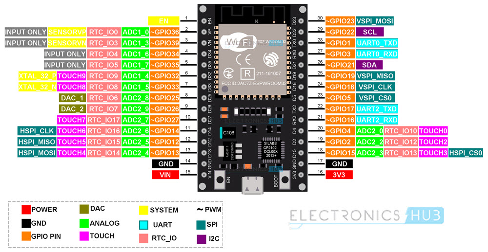
LEFT motor (aka 2):
- in1 --> 26
- in2 --> 27
- in3 --> 14
- in4 --> 13
RIGHT motor (aka 1):
- in1 --> 19
- in2 --> 4
- in3 --> 2
- in4 --> 15
Distance Sensor:
- Trigger --> 5
- Echo --> 18
Servo Pins:
- IN --> 32
- IN --> 33
- IN --> 25
If you want to have both servos and luminosity sensors attached you will want to put the servos on the Servo 1 and Servo 3 connectors (D12 and D25 respectively), and the luminosity sensors on Servo 2 and 4 (D32 and D33). This is because GPIO pin 25 cannot be used for input because it is used for the Wifi module built into the chip - but it can be used as a PWM output to drive a servo.
Right now, we have only figured out how to "bake cookies" from within VS Code. It should be possible to do all of the development steps from the command line as well - we just haven't worked on that yet.
- download visual studio code (mac and linux seem to talk to the board most reliably) -- this may involve installing some form of git.
- From VSCode, clone this repository (which should automatically install Platform IO and the ESP32 development tools)
- Restart VSCode
- Note: you will need to install git on your system to clone the repository. You will have to restart VS code after you install git.
- Note: Do not use a remote repository to clone the project. It will not work. Clone the project to your local machine. PlatformIO is incompatible with remote repositories.
- Note: you many have to install the USB driver: https://www.silabs.com/developer-tools/usb-to-uart-bridge-vcp-drivers?tab=downloads and the VCP driver: https://www.silabs.com/developer-tools/usb-to-uart-bridge-vcp-drivers?tab=downloads although modern operating systems should have the driver built in.
- Note: use the black USB cable that came with the robot. The white cable is for charging only.
Once VS Code is all settled down and ready to get some work done:
- in the Platform IO panel, select Project Tasks > esp32dev > Platform > Build Filestystem Image
- then, Project Tasks > esp32dev > Platform > Upload Filesystem Image
- then, Project Tasks > esp32dev > General > Upload
$ esptool.py -p /dev/tty.usbserial-0001 read_flash 0x8000 0x1000 partition-table.bin esptool.py v4.7.0 Serial port /dev/tty.usbserial-0001 Connecting.... Detecting chip type... Unsupported detection protocol, switching and trying again... Connecting..... Detecting chip type... ESP32 Chip is ESP32-D0WD-V3 (revision v3.1) Features: WiFi, BT, Dual Core, 240MHz, VRef calibration in efuse, Coding Scheme None Crystal is 40MHz MAC: d4:8a:fc:c6:ca:70 Uploading stub... Running stub... Stub running... 4096 (100 %) 4096 (100 %) Read 4096 bytes at 0x00008000 in 0.4 seconds (88.5 kbit/s)... Hard resetting via RTS pin...
If you are not going to use VSCode you just need to install the PlatformIO CLI by following the instructions here: https://docs.platformio.org/en/latest/core/installation.html.
If you are going to use VSCode then you need to also install the PlatformIO IDE extension for VSCode by following the instructions here: https://docs.platformio.org/en/latest/integration/ide/vscode.html#installation
You should add your user to the dialout group to access the USB serial port:
sudo usermod -a -G dialout $USERThe USB driver should load automatically and you should be able to see the USB device by running the following command in the terminal:
ls /dev/ttyUSB*and you can see the device by running the following command in the terminal:
lsusbwhich should show something like:
Bus 001 Device 004: ID 10c4:ea60 Silicon Labs CP210x UART BridgeAt this point you can use your favorite text editor to edit the code and then run the following commands to build and upload the code to the ESP32:
make
make installFor WSL2 follow the Linux instructions above.
You may also need to add udev rules for PlatformIO (see https://docs.platformio.org/en/latest/core/installation/udev-rules.html for more information). You can do this by running the following command in the Linux/WSL2 terminal:
 curl -fsSL https://raw.githubusercontent.com/platformio/platformio-core/develop/platformio/assets/system/99-platformio-udev.rules | sudo tee /etc/udev/rules.d/99-platformio-udev.rules
 sudo service udev restart
You will need to connect the USB device to the WSL2 instance. You can do this by following the instructions here:
In powershell as Administrator run the following commands where <busid> is the busid of the USB device you want to connect to WSL2. You can find the busid by running usbipd list. The busid will be in the format busid 1-1.1 where 1-1.1 is the busid. Run the following commands in powershell as Administrator to connect the USB device to WSL2:
usbipd listThe output will include a line which looks something like:
1-8 10c4:ea60 Silicon Labs CP210x USB to UART Bridge (COM3) Not sharedwhere 1-8 is the busid.
You can then run the following commands in powershell as Administrator to connect the USB device to WSL2:
usbipd bind --busid <busid>
usbipd attach --wsl --busid <busid>
Note: you will need to reattach the USB device to WSL2 every time you restart WSL2 or Windows wakes up.
You can see if the USB port is available by typing in a Linux/WSL2 terminal:
lsusbThis should include a line like:
Bus 001 Device 004: ID 10c4:ea60 Silicon Labs CP210x UART BridgeAt this point, just like with plain Linux above you can use your favorite text editor to edit the code and then build and upload the code:
make
make install